
Here’s what I’ve been talking about over the recent blog entries: The Clipping Stage!
Disclaimer: It’s still not complete; there’s supposed to be an additional capacitor and diode, but we’re testing the resistors and transistor first.
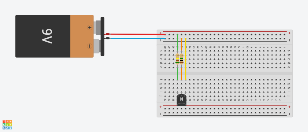
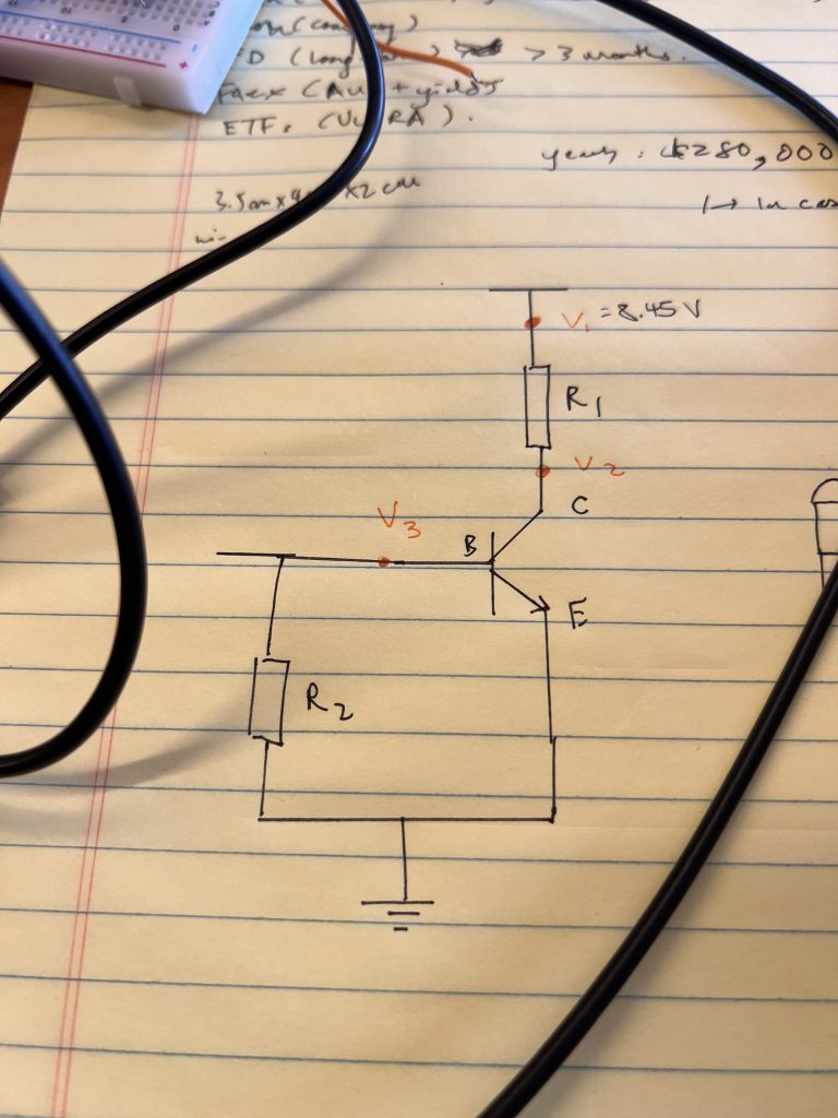
R1 is the Green Resistor, with a value of 510kΩ. It’s connected to the power source (9V) and the collector of the NPN transistor.
R2 is the Red Resistor, with a value of 1MΩ. It’s connected to the base of the NPN transistor and ground.
And we have the emitter of the NPN transistor, leading straight to ground.
The issue: V3 doesn’t have any voltage going through. We think that it’s either A) the transistor’s fault, or B) the breadboard itself, which might have short-circuited. Either way, it’s bothersome, and progress has been slow during the holidays.
Anyhow, I’ll have to get it done by this year, since I’ll be busy with my exams in the next. Oh boy.