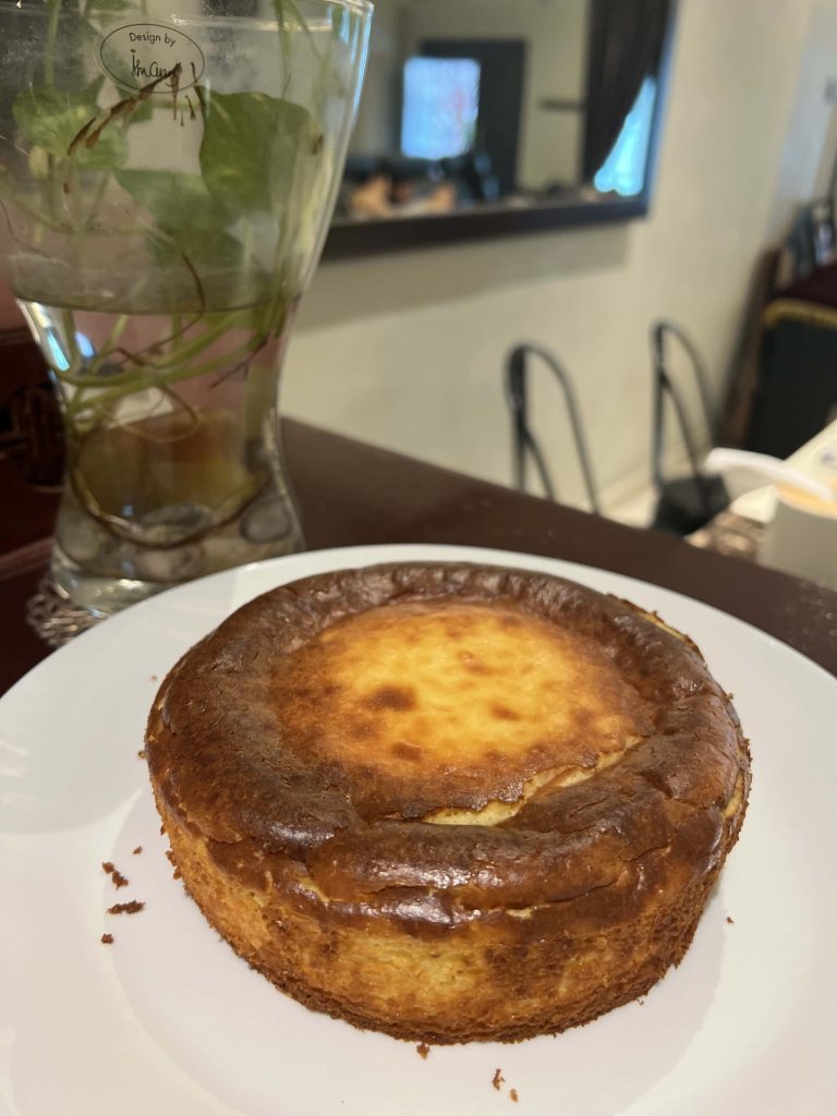
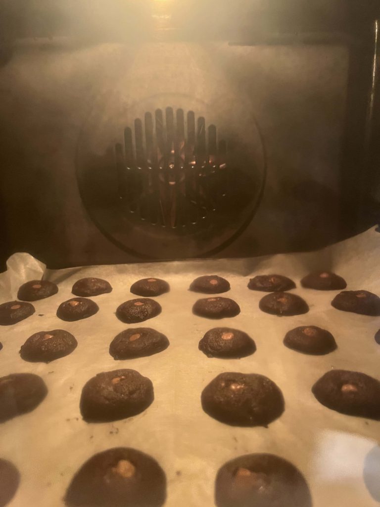
Another week, another bake. Too bad I didn’t achieve that crackly texture on top.
Another week, another bake. Too bad I didn’t achieve that crackly texture on top.
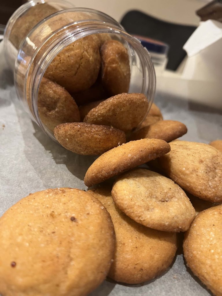
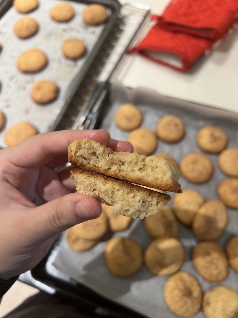
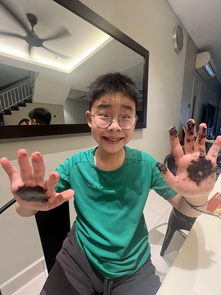
Very crunchy! I can’t really tell whether a cookie will be crunchy / chewy, to be honest. I just wing it.
These would look outstanding with more choccy chips.
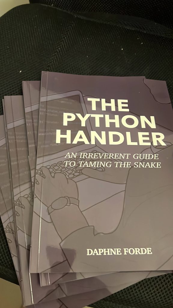
Giving out my first few (autographed) copies!
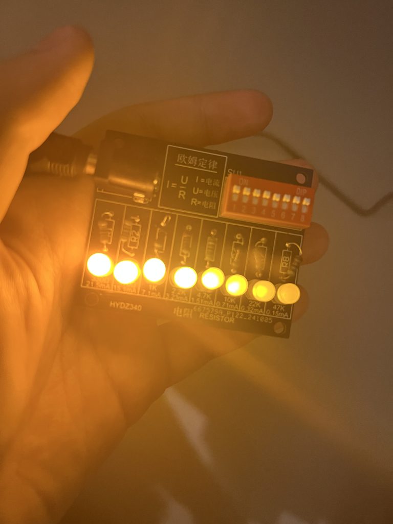
Here it is! My dad ordered it from Shenzhen. It’s a city in China, where all these electronics kits are manufactured from. So now you know.
You’ve got the power source (VCC), the switches (SW1), and the resistors and their respective LED diodes (eight paths in total).
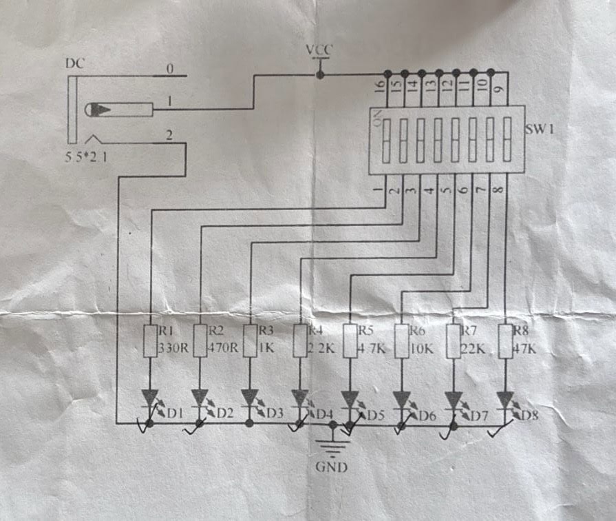
You might have noticed some numbers below the resistor names. These are called their resistance values. I’ll explain about them shortly.
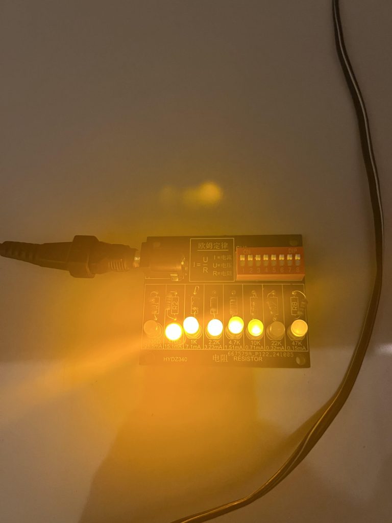
It’s quite simple: you plug in a power source (with the correct polarity, of course), flip on the switches, and watch the magic unfold. Here’s what it looks like.
Note that D1’s light is brighter than that of D8’s.
Some of you have never heard of a resistor in your lives. It’s OK. Here’s the thing: the higher the resistance value, the less current can flow through.
Think of resistors like obstacles in a flowing river. If you place a huge rock in the middle, not much water will be able to flow through since it has to find its way around it.
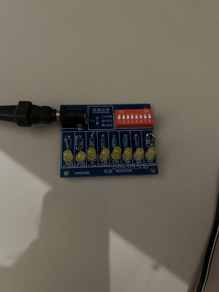
In the schematic, R1 has a relatively low resistance of just 330 Ω. From there, the value gradually increases until you reach R8, where it has the most resistance out of the resistors at 47 KΩ.
Since R1 has a lower resistance, D1 glows much brighter!
And that’s it! Here’s a cool video of me powering down the circuit. Should I write about polarities next?
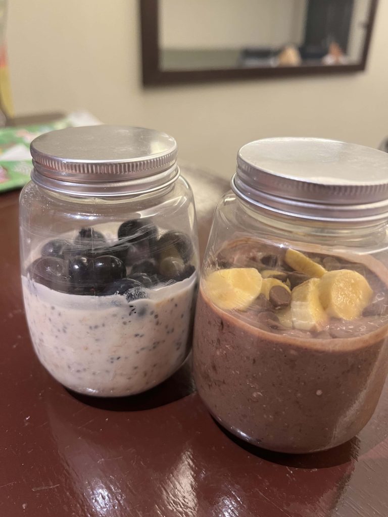
I WILL DIE ON THIS HILL DEFENDING OVERNIGHT OATS.
R1 and R7 seem funky. Will troubleshoot soon.
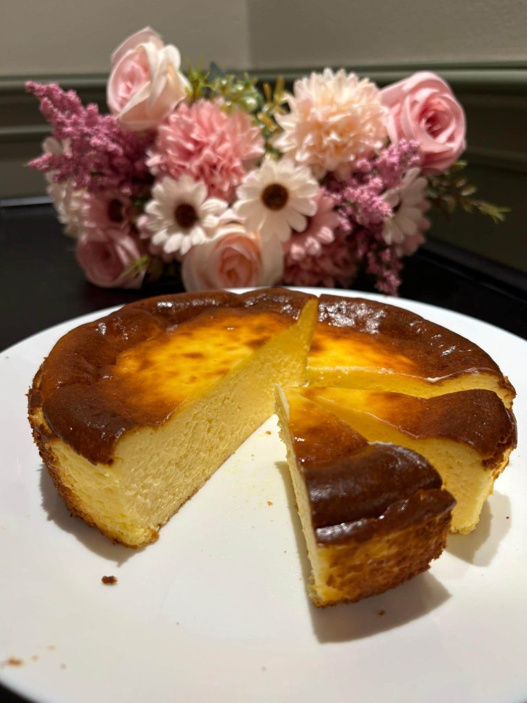
BASK in its absolute glory. Pun absolutely intended.