Contents
Have you ever paid attention to street lights? Like, reeealllyyy paid attention?
When I was eight, I used to wonder how they lit up automatically at night. Did some guy have to turn them on one by one? Sounds like a crappy job. Then I woke up the next day and forgot all about it.
Until, years later, I did an inventory run and found a packet of light-dependent resistors tucked away in the corner.
About LDRs
LDRs are resistors whose resistance decreases as light intensity increases. And when resistance decreases, more current can flow in the circuit. This means that the circuit can be designed to turn lights on when it is in bright light.
But this isn’t very practical, is it? Surely, we want lights to turn on in the darkness, rather than when it’s already bright.
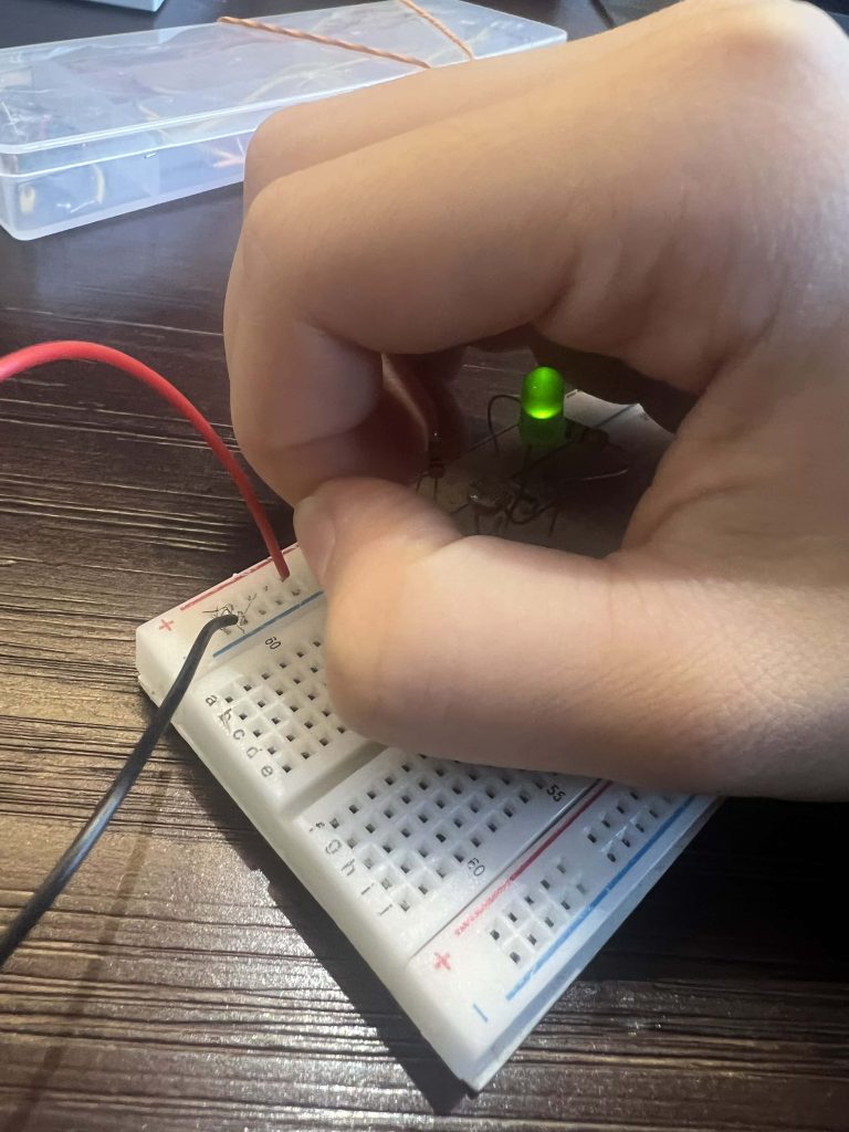
In my night light circuit, my light lights up in darkness, and you can see how it happens in the schematic below.
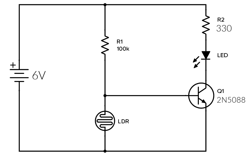
Schematic
I referred to this schematic at this very handy website.

My battery was down to 6V, so my current would also decrease. To compensate for this, I reduced the value of R2 so my LED would receive roughly the same amount of current.
I didn’t have a BC547 either, but it worked with a 2N5088, so we’ll roll with that.
Updated version:
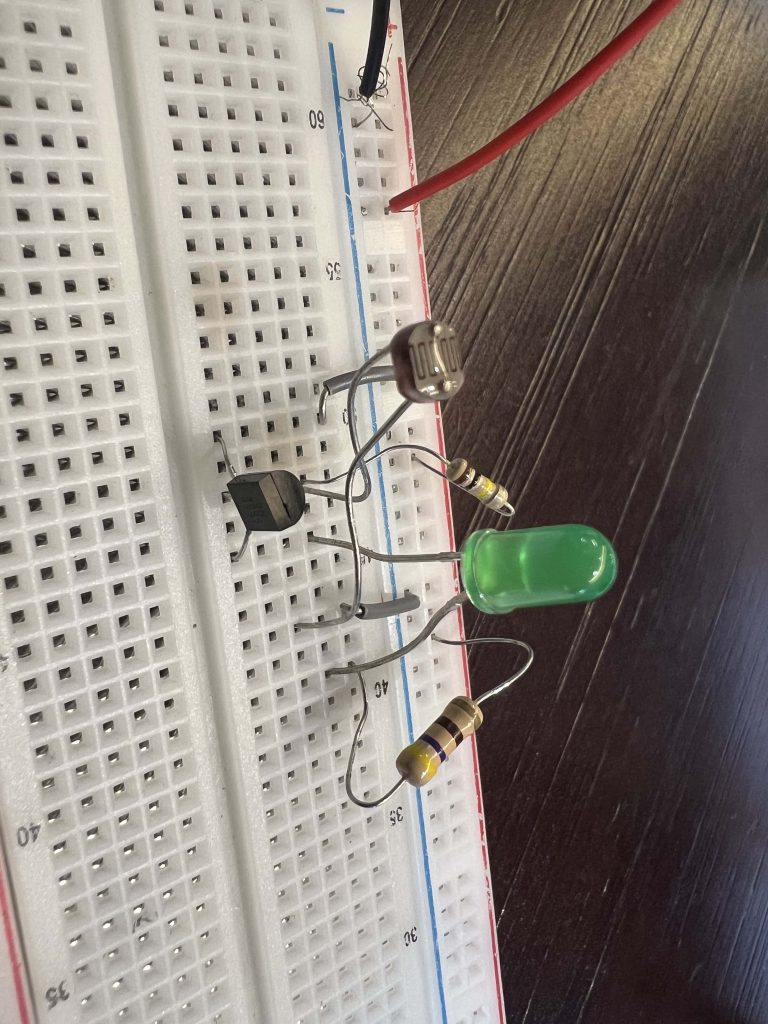
This circuit is made up of a bunch of components, including:
- A battery (6V in my case)
- Two resistors, R1 and R2 (I’m too lazy to copy/paste the Ohms symbol, so just refer to the diagram above)
- A LDR
- A 2N5088 transistor (NPN)
- An LED
The LDR and R1 form something that’s called a potential divider. They’re connected to the base of the transistor, which acts as a switch for the LED. The transistor only turns on if there’s a certain amount of voltage flowing to the base (around 0.7V). This is called transistor biasing.
In bright light, the resistance of the LDR is low. The thing with potential dividers is that the component with a higher resistance value takes a larger share of the voltage.
Since the LDR’s resistance is low, most of the voltage is taken by R1 instead. With so little voltage across the LDR, the transistor can’t be powered on, so it says off and doesn’t light up the LED.
On the other hand, in darkness, the resistance of the LDR is high — higher than the value of R1. So, the LDR takes up most of the voltage. The base voltage of the transistor increases. It turns on, allowing current to flow from the battery, to R2, to the LED, to the transistor, and to the ground!
R2 here acts as a safety precaution. It limits current to the LED so it doesn’t overheat.
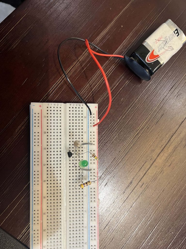
I connected the schematic on a breadboard, which are like, the best things since sliced bread.